
Guide to Tank Foundation Design for UK Sites
A tank can have the correct lining, coating, cover and pipework yet still fail prematurely if the support beneath it is wrong. This guide to tank foundation design explains the decisions that protect a commercial water storage asset from settlement, distortion, leakage and avoidable downtime. For facilities teams and contractors, the objective is not simply to create a flat surface. It is to provide verified, durable support suited to the tank, its contents, the site ground conditions and the operating duty.
Start with the tank and its operating loads
Foundation design begins with accurate information about the proposed tank. Its empty weight is only one part of the calculation. The governing load is normally the tank at maximum operating level, including the stored liquid, roof or lid system, access platforms, internal components and any imposed loads from maintenance activities.
Water weighs approximately one tonne per cubic metre. A seemingly modest increase in capacity can therefore change the required bearing performance significantly. Process liquids, acid storage and fire sprinkler water may introduce different density, temperature or chemical containment requirements. The tank manufacturer should provide confirmed dimensions, full operating weight, base loading arrangement and any specific foundation tolerances before construction starts.
Load distribution matters as much as total weight. A sectional GRP tank generally requires continuous, evenly spaced support beneath its base panels. A welded steel tank may transfer load through the shell and base in a different manner, while a concrete tank can impose substantial permanent loads across a wider footprint. Supporting a tank on isolated pads, uneven steelwork or an unverified existing slab can lead to concentrated stresses, panel movement and damaged seals.
Assess the ground before choosing a foundation
A good-looking area of hardstanding is not evidence that it can support a full water tank. Ground investigation should establish the soil profile, bearing capacity, groundwater conditions, made ground, services and risks of differential settlement. This is particularly relevant on redevelopment sites, former industrial land and locations close to drainage runs, retaining structures or existing buildings.
The appropriate level of investigation depends on tank size, consequences of failure and available site records. A small external tank on known competent ground may need a relatively straightforward assessment. A large sprinkler tank, elevated installation or underground tank requires a more detailed geotechnical review. Where an existing base is being reused, its thickness, reinforcement, condition and sub-base should be confirmed rather than assumed.
Differential settlement is often more damaging than uniform settlement. If one part of the base moves more than another, tank floors may deflect, side panels can rack and connections can be put under strain. Even minor movement can compromise a liner, jointing arrangement or pipe penetration over time. The foundation engineer must therefore consider local weak zones, variable fill material and the effect of nearby excavation or water erosion.
Groundwater and buoyancy
Groundwater is a critical consideration for underground and partially buried tanks. When a tank is empty or being cleaned, rising groundwater can create uplift forces that exceed its self-weight. Anti-flotation measures, drainage arrangements and structural calculations may be required.
For above-ground installations, groundwater can still affect long-term performance by softening subgrades, washing out fines or increasing frost-related movement. Site drainage must direct water away from the foundation without undermining the supporting formation.
Select a foundation type that suits the tank
There is no single foundation detail suitable for every tank. The correct arrangement depends on tank construction, load, site access, ground conditions, frost exposure, drainage and whether the asset is new, refurbished or replacing an existing unit.
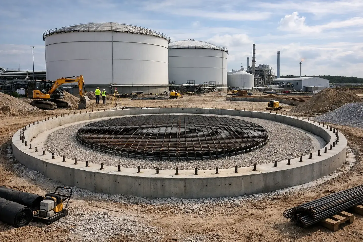
A reinforced concrete slab is commonly specified for sectional GRP, steel and packaged water tanks because it can provide a level, continuous and durable bearing surface. It must be designed for the confirmed loading and constructed to the flatness tolerances required by the tank supplier. Poor finishing, high spots, standing water and abrupt level changes should be addressed before tank assembly begins.
In some applications, a ring beam or ringwall supports the tank shell around its perimeter. This can be appropriate for certain circular steel tanks, but it is not automatically suitable for tanks that require full-base support. The tank manufacturer’s loading details are decisive. A foundation arrangement that is structurally adequate in general terms may still invalidate installation requirements if it does not support the tank in the intended way.
Engineered steel foundations can be useful where access, level differences or programme constraints prevent a traditional slab. They require careful design for deflection, corrosion protection, connection detailing and full support to the tank base. For internal plant rooms, steel frameworks may also need to account for imposed building loads and restricted installation routes.
Existing concrete plinths are often reusable, which can reduce project cost and disruption. Their condition should first be surveyed for cracking, spalling, inadequate dimensions, unevenness and evidence of settlement. Local concrete repairs, levelling works or a new overlay may be sufficient. Where the slab is fundamentally unsuitable, building a new foundation is safer than adapting the tank around a failing base.
Design for level, tolerance and drainage
A tank base must be level, but “level enough” should never be a judgement made by eye. The permitted tolerance is determined by tank type, dimensions and construction method. Sectional tanks are especially dependent on a true, continuous base because variations can prevent panels from aligning correctly and place uneven stress on the floor.
Survey the completed foundation before installation, including levels across the full footprint, diagonal dimensions and surface condition. This gives the installation team a clear acceptance record and enables defects to be corrected before heavy components arrive on site. It is considerably quicker to resolve a local high spot before assembly than after a tank is filled.
Drainage is equally practical. Water should not be allowed to pond against a tank base, around steel supports or beside pipe penetrations. Falls in surrounding hardstanding, channels where necessary and correctly positioned drainage points help keep the area serviceable. However, drainage must not route water beneath the slab or create a path for erosion of the sub-base.
For potable water installations, the foundation and surrounding area should also allow hygienic inspection and maintenance. Leave adequate working space for access hatches, valves, sampling points, external inspections and future lining or coating works. A tank squeezed into a tight corner may save floor area but can make routine compliance work more expensive for its entire service life.
Coordinate pipework, access and restraint details
Foundation work should be coordinated with the complete tank layout, not treated as a separate civil package. Incoming mains, outlet pipework, overflow routes, washout connections, electrical containment and access ladders all affect where openings, sleeves and edge clearances are needed. Late changes often result in drilling through finished concrete, compromised waterproofing or pipework under unnecessary strain.
Pipework should be independently supported where required. A tank wall connection is not normally intended to carry the weight of long pipe runs, valves or poorly aligned connections. Flexible connectors and correctly designed supports can accommodate operational movement, thermal change and minor settlement without transferring damaging loads to the tank.
Wind, seismic considerations where applicable, vehicle impact and empty-tank stability should also be reviewed. External tanks may need restraint or protection measures depending on height, location and exposure. In fire sprinkler applications, the foundation and tank arrangement should be coordinated with the wider fire protection design, access requirements and insurer expectations.
Build quality into the installation sequence
The most reliable tank foundation projects follow a controlled sequence: confirm design information, investigate the ground, construct the specified foundation, survey and sign it off, then install the tank. Rushing the first stages to meet a delivery date can create defects that remain hidden until the tank is full.
Keep records of ground assessment, concrete specification, reinforcement, curing, finished levels and any remedial works. These documents support handover, future inspections and decisions on refurbishment or replacement. They also give building operators a clearer basis for demonstrating that a critical water storage asset has been installed responsibly.
Nationwide Water Solutions Ltd assesses the wider condition of water storage installations, including whether the existing base remains suitable for a refurbishment, lining system, replacement tank or ancillary upgrade. This joined-up approach avoids spending money on a new tank solution while leaving a fundamental support issue unresolved.
When should the foundation be reviewed?
A review is sensible before installing a replacement tank, increasing stored volume, changing liquid type or adding equipment such as insulated lids, access platforms or new pipework. It is also warranted where there are signs of cracking, recurring leaks at low-level connections, uneven tank panels, corrosion at the base, pooling water or doors and hatches falling out of alignment.
The right foundation is rarely the most visible part of a water tank project, but it is the part that determines whether every component above it can perform as designed. Verify it early, design it around the actual tank and site conditions, and retain the evidence needed to manage the asset with confidence.



Comments